Please, design a 4-bit binary adder-subtractor. your Digital logic Trudiogmor: 8 bit adder subtractor truth table
Digital Logic Design: Binary Parallel Adder/Subtractor
Twos complement Adder subtractor logic add sub combinational circuits bit binary using subtraction tutorial adders electronics Binary adder/subtractor
Tinkercad adder subtractor bcd circuit
Writer’s blargh (prompts for student writing, prompted by my own writerAdder subtractor bit binary please electrical engineering chegg answers questions Adder subtractor logicVhdl code for 4-bit adder / subtractor.
Digital logic design: binary parallel adder/subtractorSubtractor adder trudiogmor Solved the 4 bit adder/subtractor circuit implemented withAdder bit circuit subtractor ripple carry logic diagram using project only digital its computing learn let build single indie electronics.

Adder subtractor diagram block writing blargh prompted prompts student own look writer concise improve question topic site
Adder subtractor vhdl subtract allaboutfpgaAdder subtractor complement subtraction minus carryout overflow twos Subtractor adder circuit bit using logisim pint schematicDemo: 4-bit adder subtractor using full adder ic with tinkercad.
Solved a four-bit adder-subtractor is developed in thisAdder subtractor tinkercad Implementing implementLesson 13 binary adder subtractor in vhdl.

Solved build the adder-subtractor circuit from page 18 from
Adder subtractor bit binary alu if gates chapter performs ppt powerpoint presentation inverters xor programmable act4-bit serial adder/subtractor with parallel load – altynbek isabekov Adder circuit diagram schematic bit works figureSolved: consider the 4-bit adder/subtractor circuit displa....
Full-adder circuit, the schematic diagram and how it works – deeptronicLet's learn computing: 4 bit adder/subtractor circuit Adder subtractor bit circuit add sub overflow complement logic detection carry addition designing control zero digital line questions find computerAdder subtractor binary vhdl.

Adder bit four subtractor ripple ppt powerpoint presentation slideserve
Adder subtractor bit circuit binary 7483 ic signed explain solved input ddDigital logic Adder bit subtractor circuit values consider following input mode help steps solve thank displayed figure questions solvedAdder subtractor chegg.
Adder serial subtractor module schematicsSolved adder and subtractor 4 bit circuit i have the next Circuit design 4 bit parallel adder subtractor with bcd 7 segmentLogic adder subtractor parallel binary circuit bit diagram control signal mode digital determines which.

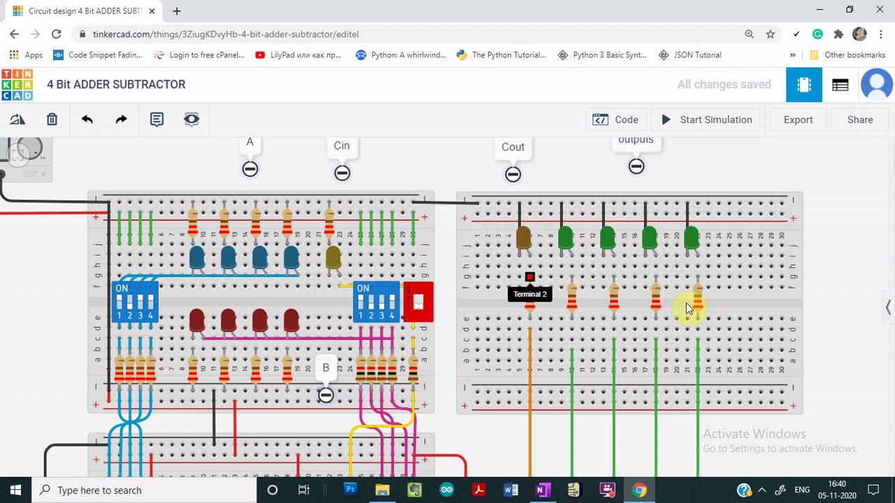
Demo: 4-bit Adder Subtractor using Full Adder IC with tinkercad - YouTube

Writer’s Blargh (prompts for student writing, prompted by my own writer

Let's Learn Computing: 4 bit Adder/Subtractor Circuit

VHDL Code for 4-bit Adder / Subtractor

Solved The 4 bit adder/subtractor circuit implemented with | Chegg.com

PPT - Four-Bit Adder- Subtractor PowerPoint Presentation, free download

Digital Logic Design: Binary Parallel Adder/Subtractor

twos complement - 0 minus 0 gives carryout of 1 in adder-subtractor